The Barn Conversion
Hopefully this section will put a little detail into the conversion.
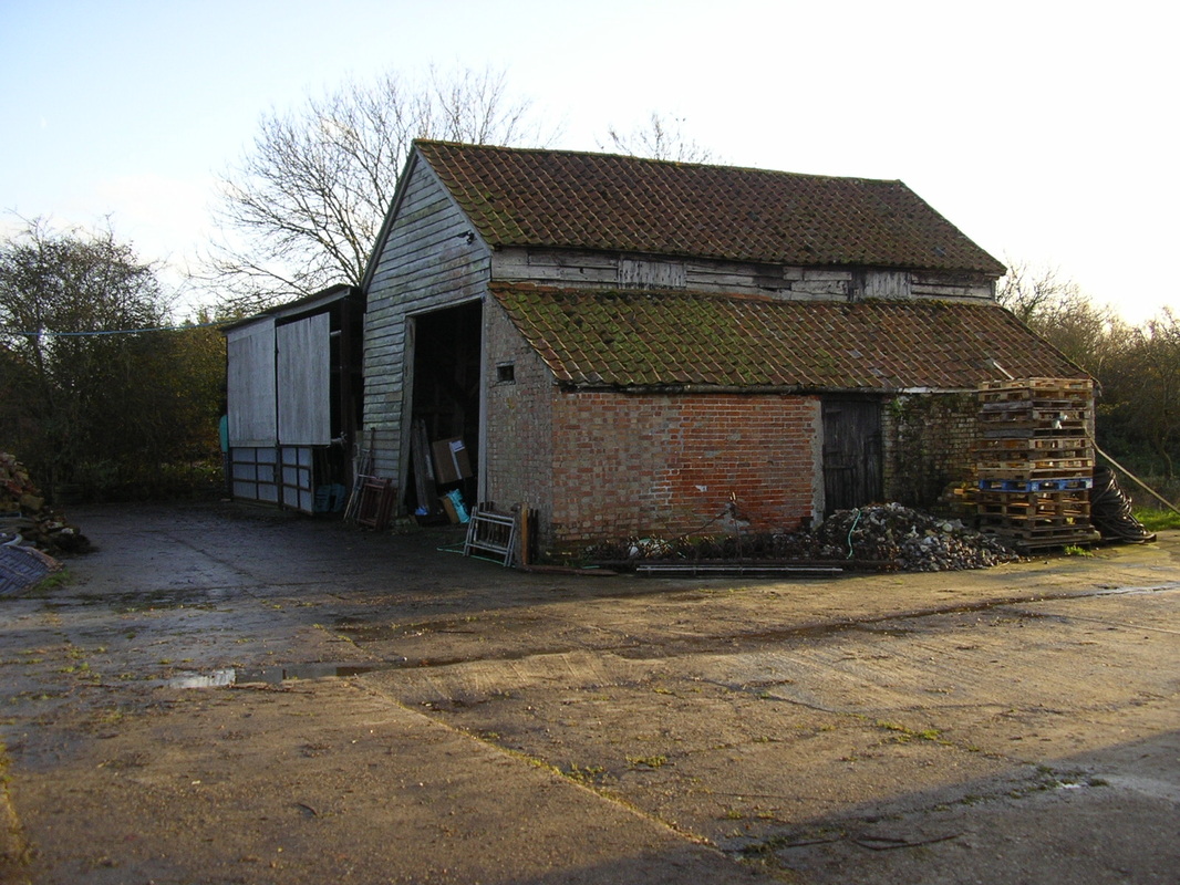
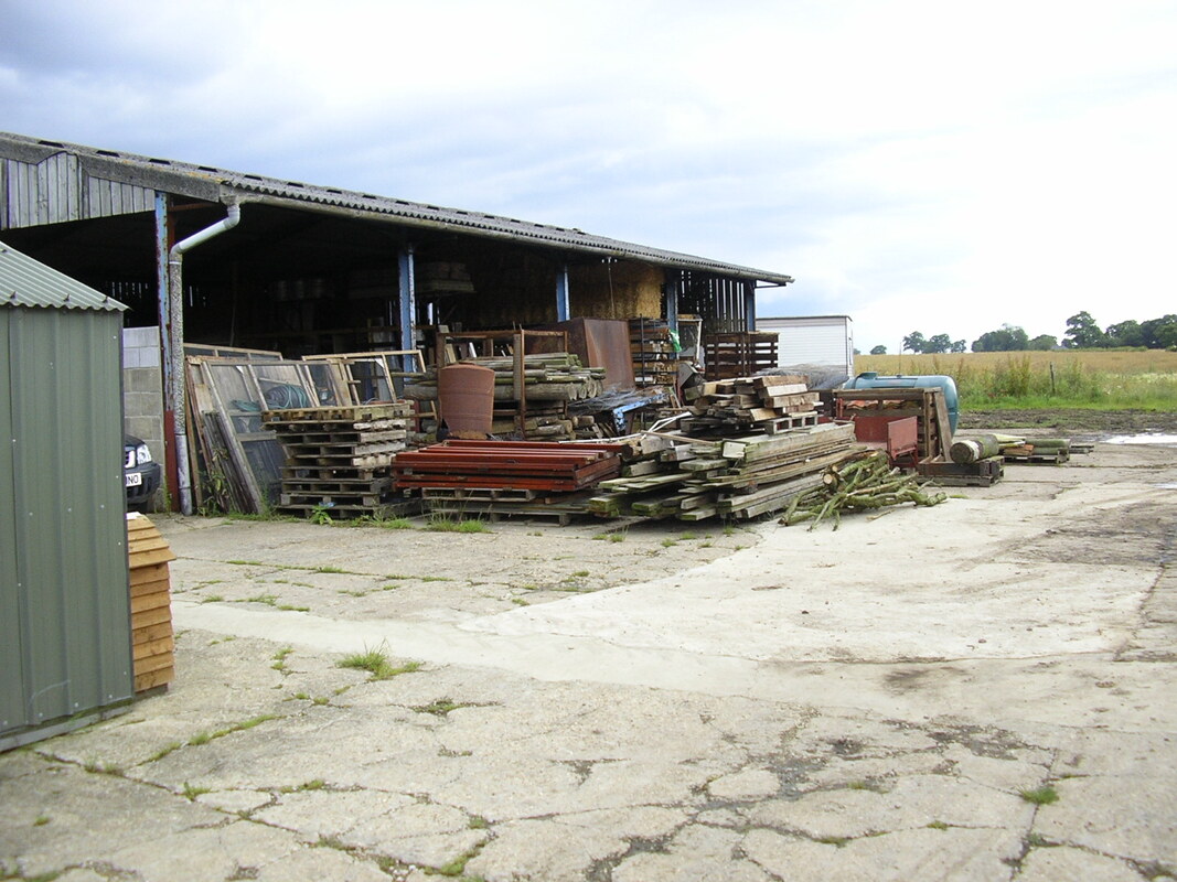
The Barn pretty much as it was when purchased in 2000. The two adjacent grain stores were added around 1985 and supplemented the Barns last use. The roofs appear quite sound but actually let lots of rain in. The lean of the Barn laying back is quite evident.
The Barn 2005
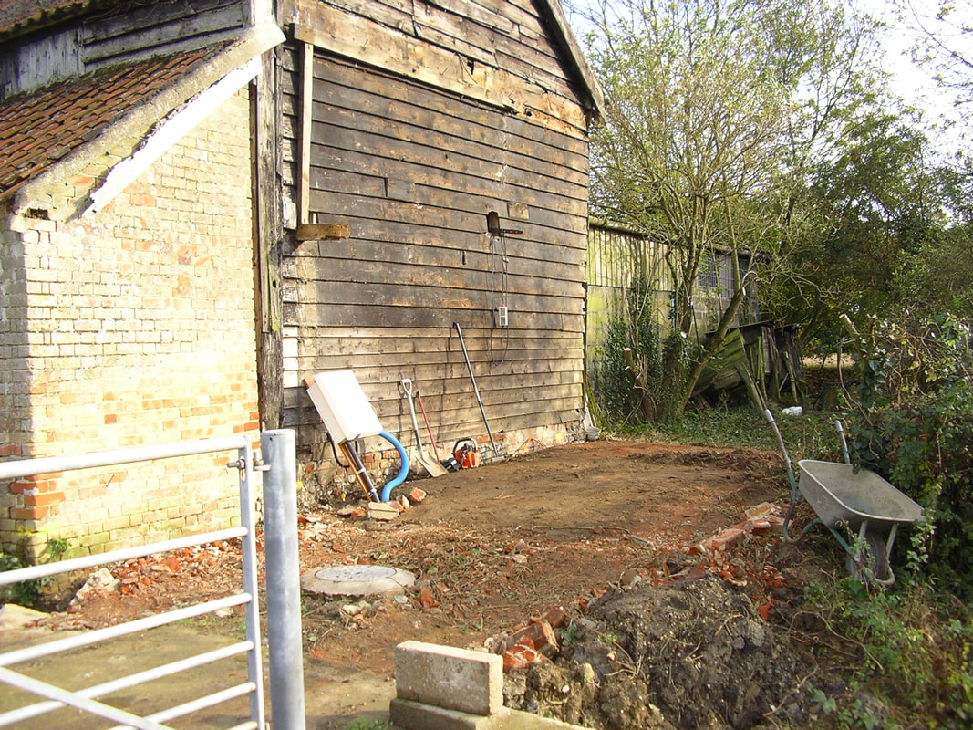
One of the first jobs was to clear away the end bedroom lean to, as this was in a dire state of near collapse. We had also got an electric supply installed, with water on the way. BT would follow with a phone line, but this would entail a six-month battle first!
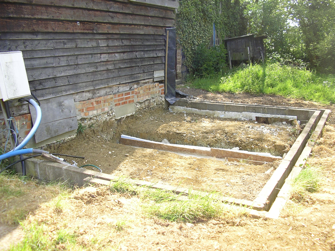
An electric sub-main and a water supply to the Cattle Shed and the planned Mobile Home would also be installed in a service duct to go in from here with the sewage drainpipe.
The manhole shown is actually a services duct. The electric meter box feeds a temporary fuse-board in the Barn and the blue duct is a feed out to the Cattle Shed, and from there into the proposed Mobile Home.
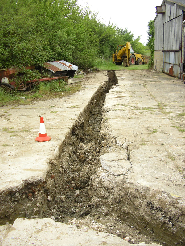
First real job is to get the sewage plant and drains in, using my JCB and trusty David Brown. It was difficult to site and required precise measurement to get a sufficient fall on the pipework and keep the overflow water level into the adjacent ditch high enough.
The old Cattle Shed is on the right, and on the left old farm machinery which littered the place when purchased.
The old Cattle Shed is on the right, and on the left old farm machinery which littered the place when purchased.
Moving Over 2006
The start of selling the bungalow and moving into the mobile home.
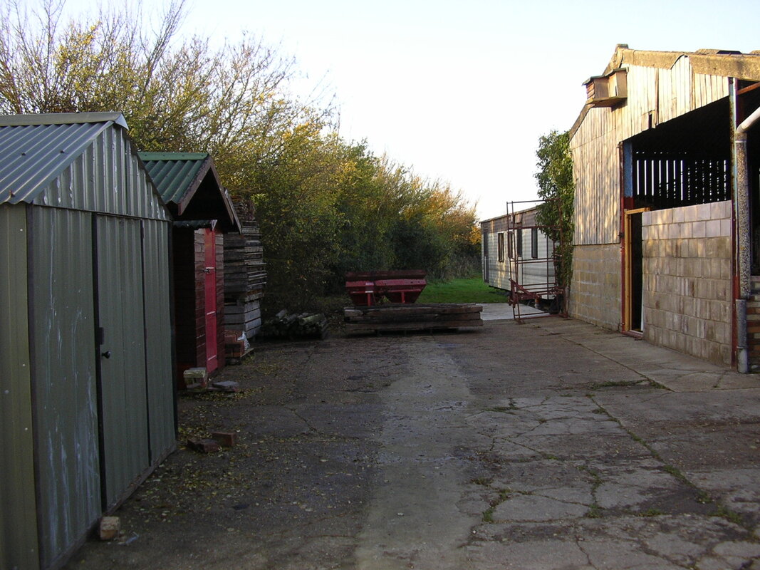
The sewage system is now in under the new concrete pad in the distance, with the trench for the pipework now concreted over. Note the sheds on the left used to store our possessions, and the start of converting the end bay of the Cattle Shed into a Workshop.
The mobile home is now in position.
The sewage system is now in under the new concrete pad in the distance, with the trench for the pipework now concreted over. Note the sheds on the left used to store our possessions, and the start of converting the end bay of the Cattle Shed into a Workshop.
The mobile home is now in position.
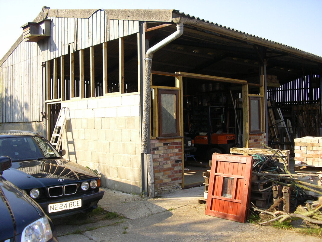
The state of the Cattle Shed having moved the contents of 4 acres into our new area of three quarters of an acre. The shed itself is also full!
The most important first job was converting the end bay of the Cattle Shed into a workshop. This was fully insulated for year-round use. About this time I also acquired a Toyota diesel Forklift, the orange one inside – one of my best ever decisions that would be in daily use on the conversion and everywhere else.
The Barn 2007
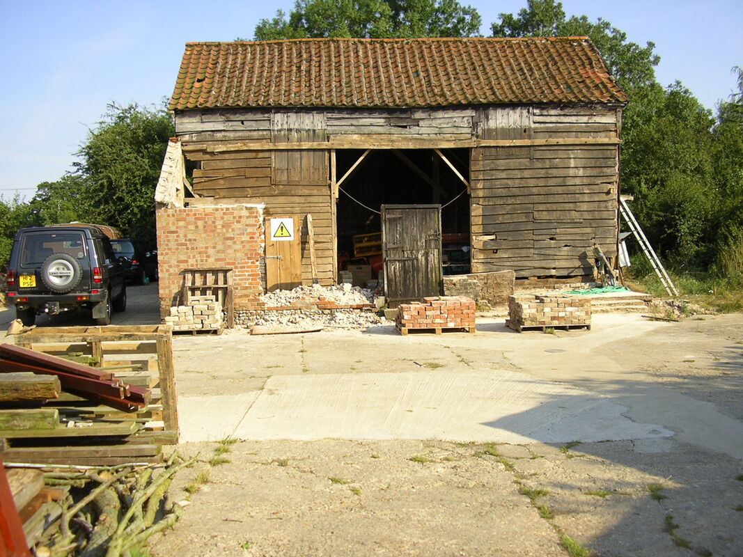
Here the front lean to is being removed. As with the end one, this needs rebuilding to meet Building Control requirements. The bricks and timber will be recycled. Note the two pitching doors in the side of the Barn, and this picture really shows the state of the main roof, the next job being to remove these tiles to take some weight off the Barn. Note as well the flint base to the wall, this will be replicated in the conversion. The new build lean-to’s will have flint faced blocks at the base of the walls, and I will build a new flint base to the Barn under the new timber frame.
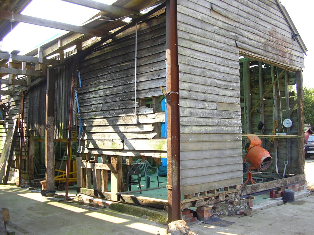
The Barn 2008
Now left with just the original Barn, work gets underway. The main job is to dig up the old concrete floor, cut out nibs under the walls, and lay a concrete plinth with steel reinforcement. This will support the Barn as a whole, all floating on the concrete base, without any actual footings being dug. The oak beams providing the base for the walls are rotten in many places and require replacing. This involved jacking up the barn in different places whilst these are replaced, sometimes with jacks, sometimes with the forklift. Horrible nerve-racking job, before which I added a load of timber bracing as added support to the structure.
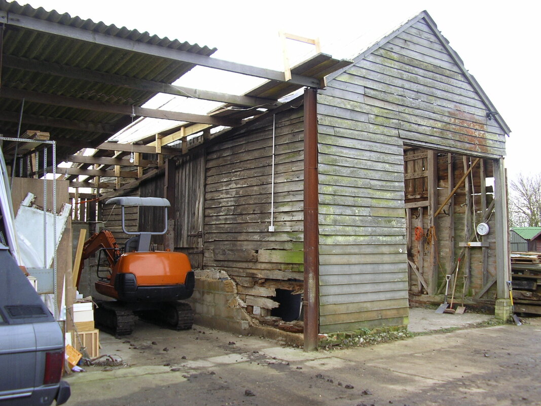
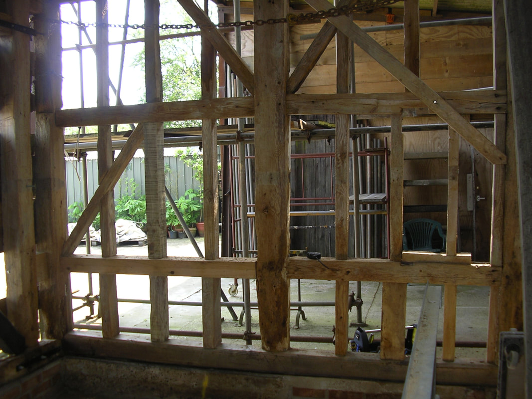
In this picture half the roof of the adjacent grain store has been removed and a platform made to work on this side of the roof. The health and safety policy was just not to fall off. Inside the door you can see a new temporary brace timber, and under that two timber hooks likely used for harness.
Adjacent the digger you can see the block and concrete wall of the grain store, and the devasting effect it had on the base timbers behind. The original Barn door is behind the digger.
This is the work in progress picture of the area above. The low wall has gone, the Barn having been jacked up to fit the damp proof course and replace plinth timbers. In the centre part of the picture the beam part missing has been replaced with a timber plate on the hidden side, and suitable replacement beams are being fitted. The floor has now been replaced with nibs added under the walls. On the end wall a new beam has been fitted under what will be a window, sitting on a brick wall and you can see a bottle jack by the bucket holding up the end of the Barn. Across the door you can see a batten brace.
On the corner around the vertical RSJ is a chain tied around the Barn beam in that corner, acting to catch the Barn should it start to move. By the Acrow by the centre of the side wall you can see a ratchet strap that is hanging the Barn off of the grain store steelwork. A lot of the lifting was done by the forklift. It was all very precarious and Heath Robinson but with a lot of thought and contingency measures relatively safe, but nevertheless heart in mouth stuff.
On the corner around the vertical RSJ is a chain tied around the Barn beam in that corner, acting to catch the Barn should it start to move. By the Acrow by the centre of the side wall you can see a ratchet strap that is hanging the Barn off of the grain store steelwork. A lot of the lifting was done by the forklift. It was all very precarious and Heath Robinson but with a lot of thought and contingency measures relatively safe, but nevertheless heart in mouth stuff.
The Barn 2010
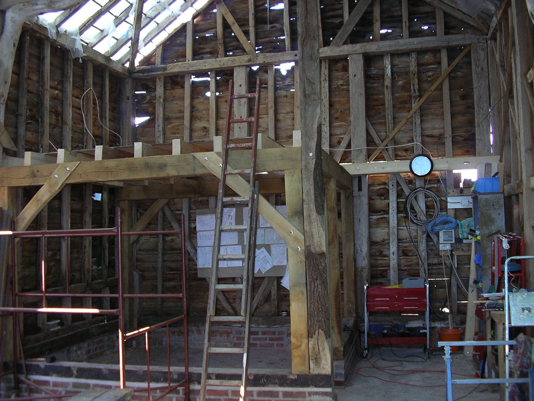
The green oak was sourced from a specialist supplier near Milton Keynes, and work commenced on adding the necessary timbers to meet the structural engineers’ requirements. I was keen to get the internal frame in place to support the barn, as it was moving quite a bit in high winds. The frame provided the walls for the Study, and the support for the Bedroom above, and would provide an excellent brace for the existing Barn structure. Not being any sort of carpenter, this was all new, and the oak beams could only be lifted by two people. The frame comprised adding haunches as braces, cut into the beams. They needed to be square, but accommodate the lean of the Barn, which was a long way off vertical, it having moved several times over the years.
We started with one long additional timber from floor to roof, part structural, part feature. This was one piece but was cut behind the cross beam to accommodate fitting. This had to be erected and taken down several times before it fitted, which was an hour’s work with the forklift every time. Two oak haunched sections were made up on the Barn floor, after offering up the sections individually and tweaking to fit their respective locations. Once made these were disassembled, and fitted piece by piece for the front section, but as a complete unit for the rear one. All butt joints were held in place with 12mm threaded studs held in place with epoxy resin. This took ages and was only possible using the forklift to move the sections as required, until they eventually fitted properly.
Given my first experiences with a band saw and router, I was quite chuffed with the result.
The floor joists were fitted to brace the box section and the single beam on the back wall which will support the floor was fitted to brace the end wall. Eventually it was found a step landing was required to give sufficient headroom and the end of this beam was removed to the right of the clock. Throughout the conversion ideas changed and plans were modified to suit new problems.
The Barn 2011
Work this year included getting the final footings in for the lean-to additions to be rebuilt later, as well as carrying on with structural works inside. This included adding structural vertical beams into the front doorway and the doorway on the Hall side of the Lounge. We devised a way to lift the beams by tying to the forks on the forklift and fixing by using 12mm rods as internal dowels resin fixed. All means to an end devised as we went along!
By the end of the year we were out of the ground and with a better structure but had nothing really much different to show for it! Family and friends kept asking when we were going to start the Barn, which was a bit frustrating.
By the end of the year we were out of the ground and with a better structure but had nothing really much different to show for it! Family and friends kept asking when we were going to start the Barn, which was a bit frustrating.
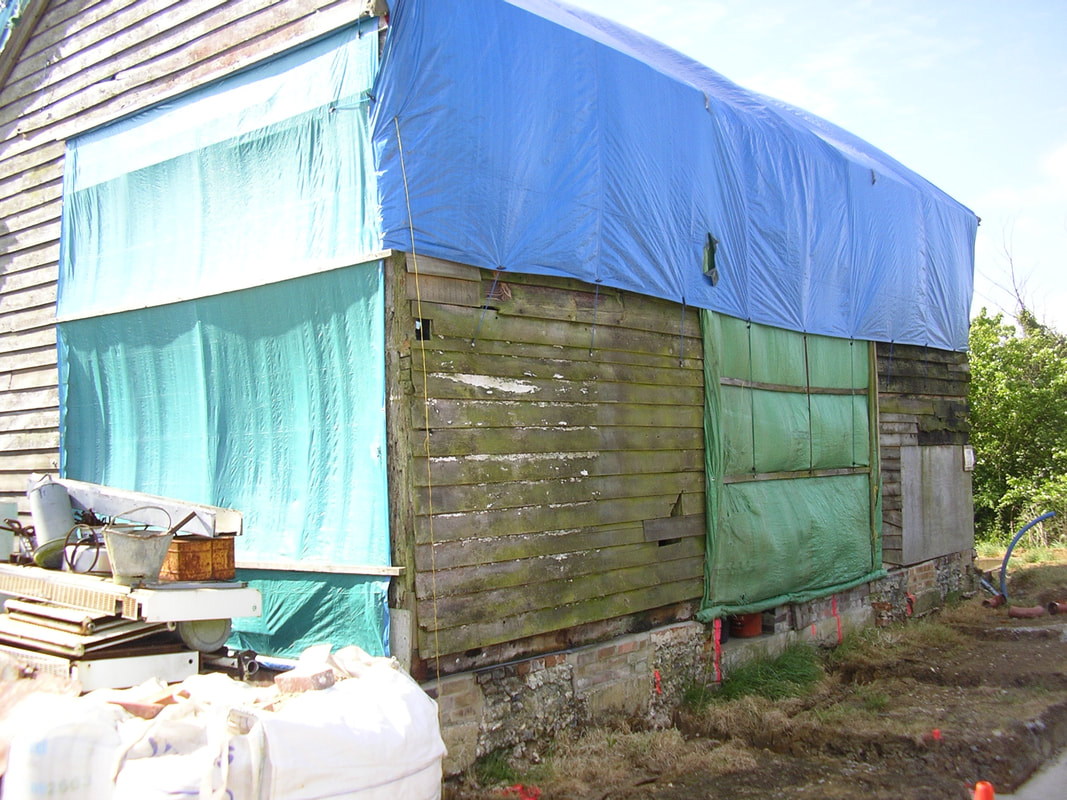
Tarpaulins were a constant battle. We had no real access to this side of the barn and had to rope tarpaulins over the roof but were unable to batten them down on this side of the roof. We purchased better tarpaulins every time which had a longer life, although a high wind could easily destroy one.
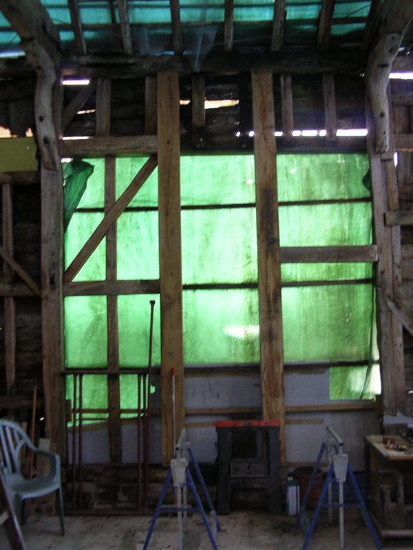
The two later doorways were to be blocked in, shown here what is to be the Hall wall, and on the field end which will be a window. We inserted two vertical green oak beams to this one, with one third of this one infilled to be the Kitchen wall, the remainder a door and glazed panels. Over this one I replaced the vertical beams that had been cut out into replacement cross members. These crossmembers were at the height of the outside lean-to roof support, and a single long structural timber had been fitted on the outside to brace this side of the Barn. At the base here we built a low wall and fitted a plinth beam.
The green oak had been air dried before purchase, but we kept it a couple of years dry and ventilated to prepare it further. This was the case with all timber, being stored dry, then moved into the warmer Barn for a month to finally dry before fitting. This has proved worthwhile as there has been virtually no shrinkage since the build. Another benefit of a DIY long build which a conventional builder can not replicate due to time restraints.
The green oak had been air dried before purchase, but we kept it a couple of years dry and ventilated to prepare it further. This was the case with all timber, being stored dry, then moved into the warmer Barn for a month to finally dry before fitting. This has proved worthwhile as there has been virtually no shrinkage since the build. Another benefit of a DIY long build which a conventional builder can not replicate due to time restraints.
The Main Bedroom footings. The outer wall on the right needed 2.5 metre footings to meet building regulations, that’s 2.5 metres more than the last build, although after maybe a hundred years that was falling over a bit. The polystyrene on the far wall is the clay heave, to allow for ground swelling and contraction. The sleeper wall in the centre was a later addition, it being undecided on a solid or concrete floor when the original footings were laid. I could have gone for either but went for timber as it was easier to accommodate services in the void.
Note on the Barn the two concrete nibs supporting the walls, and the original flint footings literally built on top of the ground.
Note on the Barn the two concrete nibs supporting the walls, and the original flint footings literally built on top of the ground.
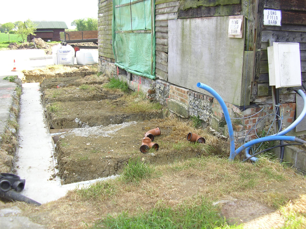
The Kitchen / Hall / Bathroom footings. These, being further from the ditch and away from trees, were shallower, 1500mm in the foreground rising to 1000mm at the far end. Having decided on a suspended floor the sleeper wall footings were cast at the same time.
Note the five concrete nibs from the Barn floor slab and the new brickwork over. The services were a nightmare here as all drainage, water, electric, phone and comms entered in this corner.
Note the five concrete nibs from the Barn floor slab and the new brickwork over. The services were a nightmare here as all drainage, water, electric, phone and comms entered in this corner.
The Barn 2012
Most of this year was spent on structural repairs to the existing timber frame, getting the scaffold up, and starting the roof.
The above photograph shows the timber frame in the course of restoration. Much of the existing secondary timbers were replaced with old timbers acquired from various places, including re-using timbers previously removed from elsewhere. In this area almost 50% of timber needed replacing.
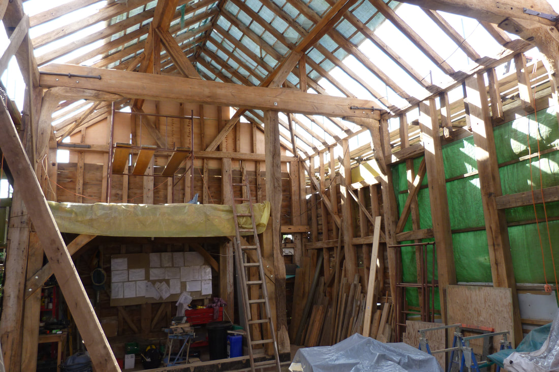
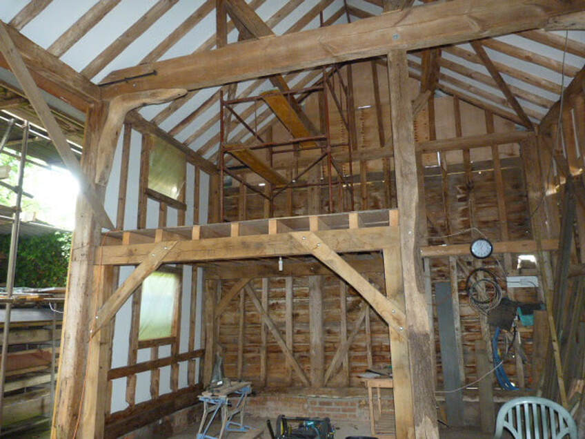
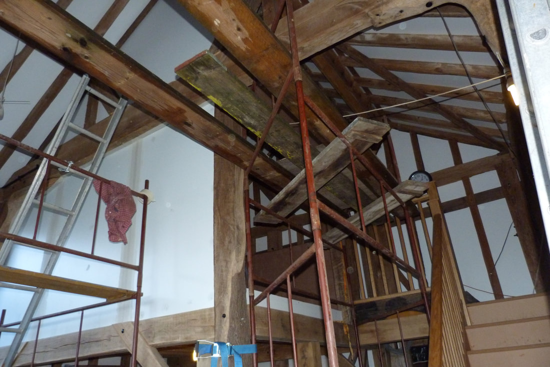
The inside of the Barn. Most of the timber has been pressure washed and lightly sanded by now and sprayed with a coat of Cuprinol preserver. On the cross beams the steel ties shown on the far beam are original, and the one top right on the near beam added, as were several others, as a very early job. Note the timber brace on the left supporting the lean of the Barn. On the roof the lower tile battens have been removed working up the roof. The plastic covers are due to pressure washing the roof timbers. The ply boarding at the far apex is part structural bracing and part weather proofing. This picture gives a good view of the knee braces supporting the cross beams.
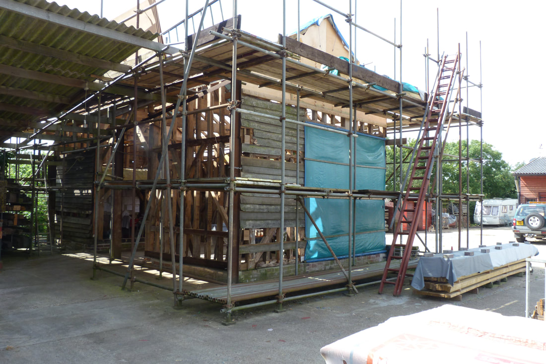
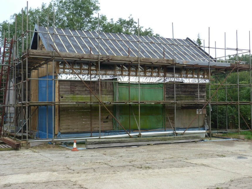
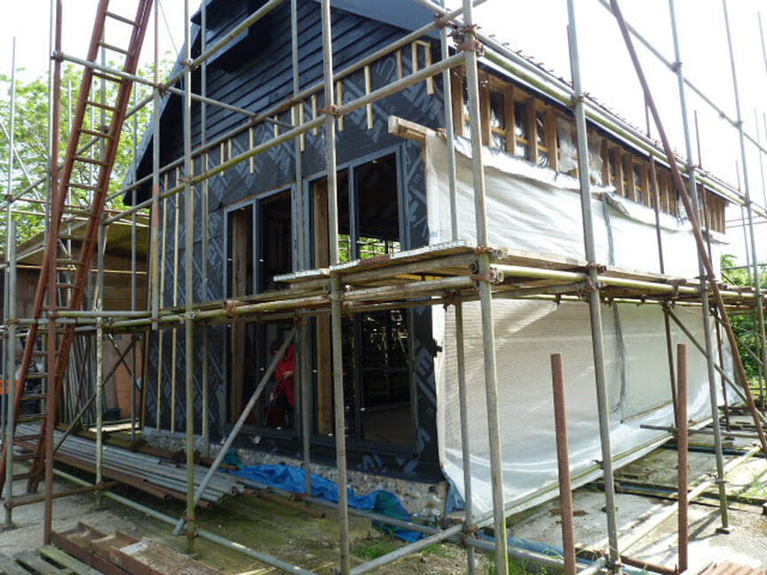
The above pictures show the completed scaffold around the Barn, a first time for me and a steep learning curve in becoming a scaffolder! Various structural repairs being undertaken on rotten timbers, and the higher level cladding being removed and the timber frame cleaned up and pressure washed. Gradually this moved up to the roof, which consisted of removing the old battens and cleaning up the roof rafters. This was done in stages, initially working off the scaffold, then putting crawl boards over the roof with battens as footholds, and working higher up, until eventually reaching the apex. This was an unconventional approach which worked extremely well, and meant I could work without climbing ladders!
The lower cladding has been left on where possible to keep some weatherproofing, and is only removed when essential for access. The whole of the barn has been pressure washed from the inside, with the timber frame being washed from the outside as it is revealed working mostly from top to bottom.
The lower cladding has been left on where possible to keep some weatherproofing, and is only removed when essential for access. The whole of the barn has been pressure washed from the inside, with the timber frame being washed from the outside as it is revealed working mostly from top to bottom.
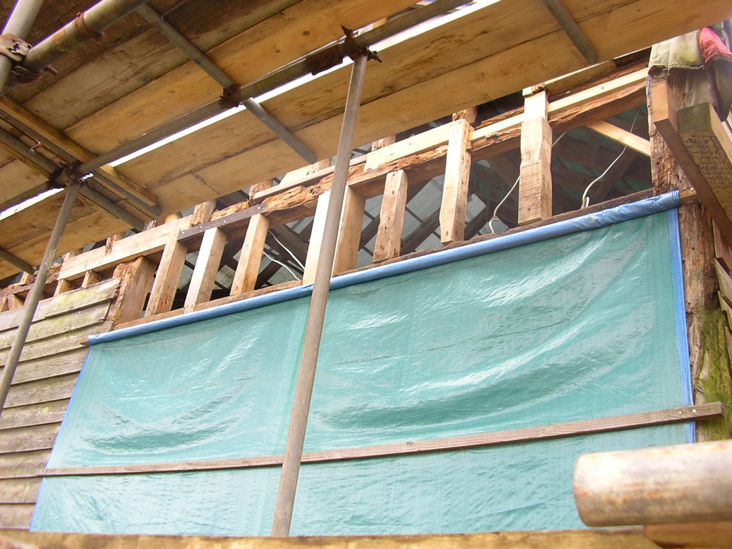
Some of the main timbers were in a very bad state but were so integrated into the structure that replacement was impossible. In these cases, structural repairs were carried out from the outside, using a laminate process of putting strength back into the rotted frame by adding layers of timber and sometimes metal braces into and behind the existing timber facade visible from the inside. This particular beam was really bad as it had been subject to water pooling over the years. In this case the ply sheeting added strength and the timber outer frame was positioned to add targeted strength to the weakest points.
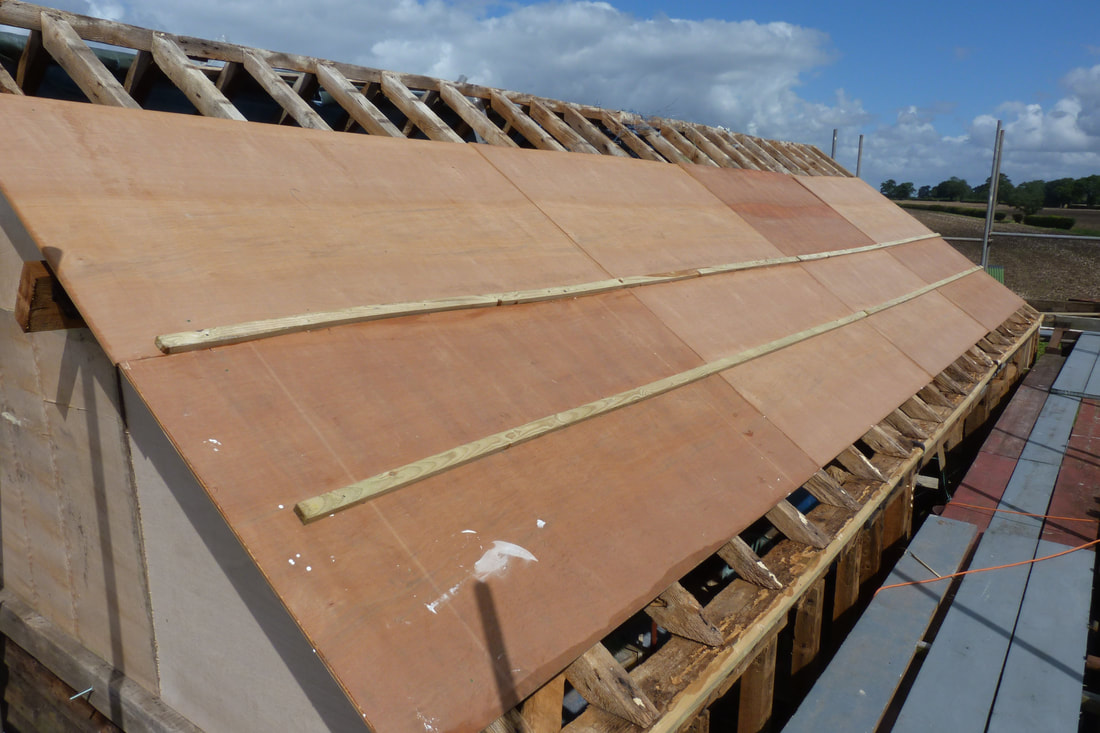
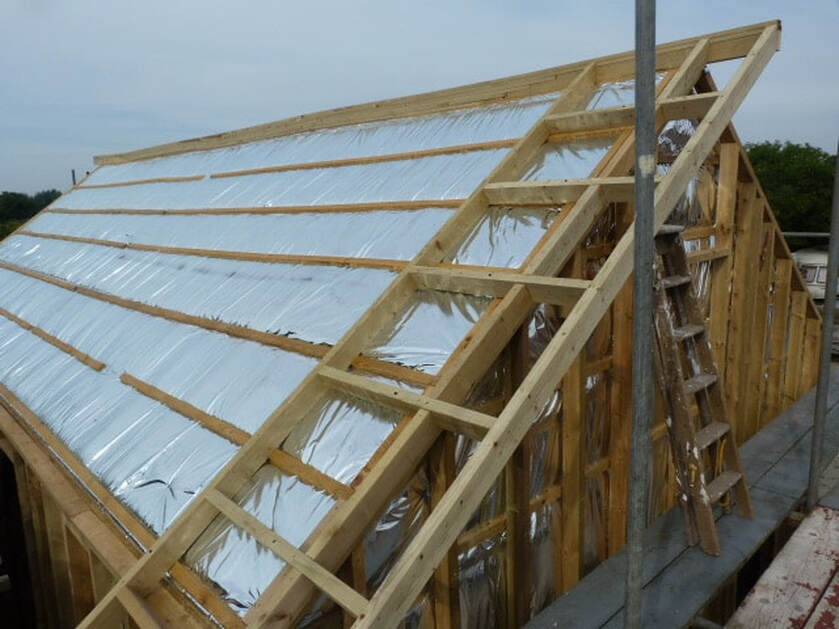
Working on the roof consisted of stripping the rafters from the bottom up and placing crawl boards over the lower sections to work further up. The apex was the most difficult to access, but we got there in the end. The biggest difficulty with the roof was the near constant rain, and the hour it took to get the tarpaulin rolled up to gain access. None of the rafters required replacement, but particular attention was paid to the strength put into the outer frame put over the existing structure, effectively building a new self-supporting structure over the old Barn. The roof had sagged and twisted over the years, and this was maintained in the new structures. The dip in the centre roof both sides made fitting the gutters a nightmare, more so on a twisted run.
The Barn 2013
This was the year we made the most visible progress and got the main Barn weatherproof.
This was the year we made the most visible progress and got the main Barn weatherproof.
Whilst the inside hasn’t actually changed, getting the plasterboard and ply on gave it a finished look and immense strength. The walls took 8’ by 4’ plasterboard and the roof 6’ by 3’, with all the ply being marine grade 12mm 8’ by 4’. The plasterboard was given three coats of bathroom grade brilliant white in the adjacent building, used as the Barn workshop. Then it was taken up to position on the Barn and cut to size. The sheets used fitted really well and only one area on one wall needed a beam added to cover a join. As the roof had a join midway each side, I pondered long on how to hide this. In the end I fitted an oak stained plywood fillet behind the roof purlin and making a feature of it actually hid it really well. All the edges of the ply were painted with a timber sealer and sealed with silicone mastic after installation. The positions of the rafters and beams were lined on the ply and in all there were only a half dozen that missed. Screws were used throughout, there are no nails anywhere.
After the ply and plasterboard, the whole was battened, covered with multi-foil and cross battened. This gave an impervious barrier with an insulation value equivalent to 100mm of Celotex. All joints were taped with reflective tape. Over this was placed a 2” by 4” timber frame fixed through to the plywood and in structural areas fixed with long Timberdeck screws into the Barn timbers. Having seen the problems caused by a flush roof I added a good overhang to protect the walls. The voids between the timbers were filled with 100mm Celotex insulation, with mastic to the edges. Effectively there are five water resistant layers all over. The open area on top of the steps is to fit a part recessed Barn Owl box as a part of the build. Note the wavy ridge board, actually made up of battening with timber at the ends.
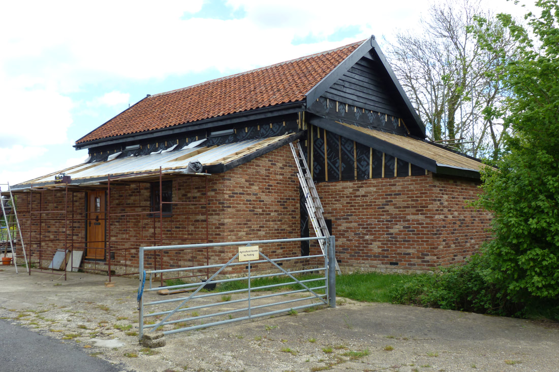
Getting the roof on was the priority, and here we have the frame finished and the breathable membrane fitted with battens. The facias on the gable ends are finished and ready for cross battening for tiling.
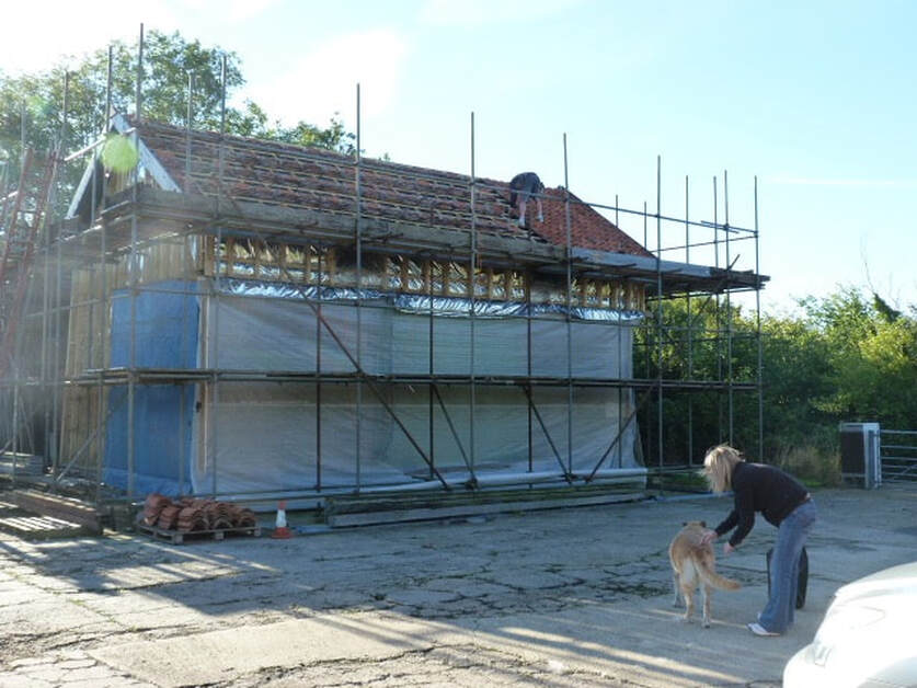
Luckily my daughter’s boyfriend at the time was a roofer, so he came and gave us a hand for a weekend. It took no time at all to get the new pantiles on the other side, but ages to fit the old pantiles shown above. I had not realised that there were four variations of pantile with three sizes on each variation. Hence the fitting was a nightmare. Once completed I then spent a complete week bedding in the tiles with silicone and fettling the fit.
The Barn 2014
Again, great strides forward in many directions this year.
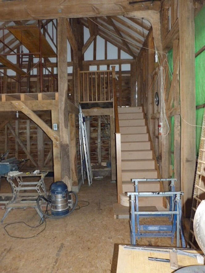
A big step up inside was fitting the staircase. I can never understand builders fitting the staircase last and building with a ladder, so it was stairs first for us.
We found a carpenter not too far away that made up a kit for me to self-install, it came in a hundred pieces but importantly the newel post joints were cut and had been made up. It was not without problems as the spindles were larger than the guides, but with some fettling it came together. Apart from the treads and risers it was oak and received several coats of clear polyurethane. It was very bespoke in having to comply with building regs and fit the available space. Importantly it also tied together the corner structurally.
We found a carpenter not too far away that made up a kit for me to self-install, it came in a hundred pieces but importantly the newel post joints were cut and had been made up. It was not without problems as the spindles were larger than the guides, but with some fettling it came together. Apart from the treads and risers it was oak and received several coats of clear polyurethane. It was very bespoke in having to comply with building regs and fit the available space. Importantly it also tied together the corner structurally.
At this point the cladding was going up and the scaffold coming down.
We had bought the oak cladding several years before and it had been air drying. It was then coated with two coats of Sadolin black prior to installation, the cuts coated during installation, and a final coat after. It was secured with stainless steel screws at the correct point – this is important to allow the timber to move. We had to start halfway up in order to get the end apexes done, so there was a fair bit of calculating going on in order to fit it in part reverse order!
We also needed to fit the windows in order to fit the reveals to clad up to, and to get the windows in using the scaffold. Hence the scaffold came down slowly and in the right order to keep access where needed, plus some alterations along the way for specific areas.
Some areas we could not progress, either internal walls, or as shown on the right, over roofs that had yet to be installed. On a new build all dimensions are known at the start, but with a Barn the top of a side roof is guesswork until it is actually fitted.
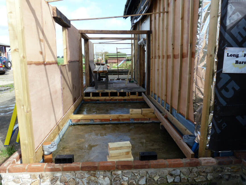
Next on the agenda was rebuilding the lean-to extensions. Here the Kitchen / Hall / Bathroom is started with the timber framed internal walls and timber floor. The centre section frame is beams that will be visible on completion, the target being to keep the Barn feel to even the new build parts. Again, an old timber lintel is fitted over the Kitchen window, with sufficient overhang to protrude past the battens and foil yet to be fitted.
Note the concrete oversite and damp-proof course in the floor and a split-level damp-proof course between inner and outer walls. The floor level had to be calculated to allow for a 50mm services void, an underfloor heating area, and a total of three flooring layers, all below FFL. Everything had to be calculated to the mm with copious drawings and often mock-up samples.
The flint blocks were a good find, giving a good base to the wall whilst maintaining the original flint finish.
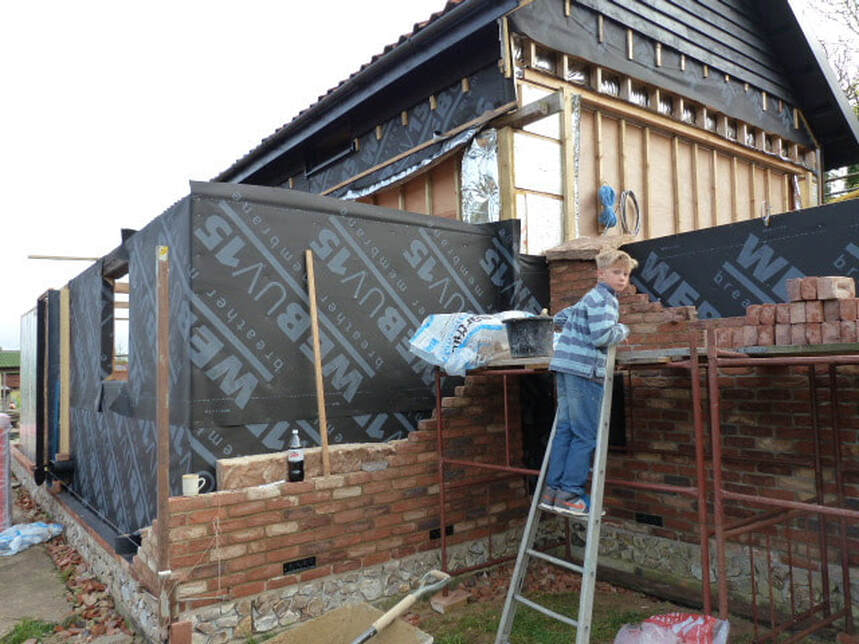
Here we have our young bricklayer, well, our grandson at least inspecting his Dads work. The Cottage mix bricks went in well and look authentic. The ornate air bricks were off eBay, as were many things, and add the necessary attention to detail to the build.
Note the Barn walls are as far as we can go until the roof is on.
Note the Barn walls are as far as we can go until the roof is on.
The Barn 2015
This year continues much as before, with targets of getting the last two roofs on and moving forward inside during the winter months. With Barn windows fitted and blocked up doorways at least it could be warmer winter working.
Inside it was a matter of getting the Study and Bedroom 2 fitted out. Problem was I had avoided needing a plasterer so far and didn’t relish the thought of someone getting plaster all over the wood beams. Added to this I needed to build high level walls completely one by one, and no plasterer would just pop in for just an hour’s work. So, the only option would be to build a section off a scaffold and plasterboard and skim and paint it myself as I went.
Two sections are done in the photo, with a third section about to start. The scaffold looks precarious but was safe, there being little room with the adjacent staircase.
Despite my lack of plastering skills it went well and looks ok from a distance!
Two sections are done in the photo, with a third section about to start. The scaffold looks precarious but was safe, there being little room with the adjacent staircase.
Despite my lack of plastering skills it went well and looks ok from a distance!
Outside we progressed with the lean-to re-build, with the roofs taking shape. The rooflights in the Kitchen & Bathroom were a nightmare, I worked them out so carefully and left oversize holes to give me some movement. Then I worked out the lay of the tiles to get them to line up and avoid cut tiles. I measured and treble checked, then measured again. Then when I was absolutely certain I finalised the holes and fitted them, with more final checking. One worked out perfectly, the other was a disaster and needed all the tiles cutting, not easy with Pantiles!
The front door was another bad choice. It wasn’t cheap at about £700 all in, and it had many coats of polyurethane to seal it and was solid engineered oak. Regrettably it was too exposed and despite several times removing it and trimming it I couldn’t stop it jamming. After a year we replaced it with a German black composite door.
The front door was another bad choice. It wasn’t cheap at about £700 all in, and it had many coats of polyurethane to seal it and was solid engineered oak. Regrettably it was too exposed and despite several times removing it and trimming it I couldn’t stop it jamming. After a year we replaced it with a German black composite door.
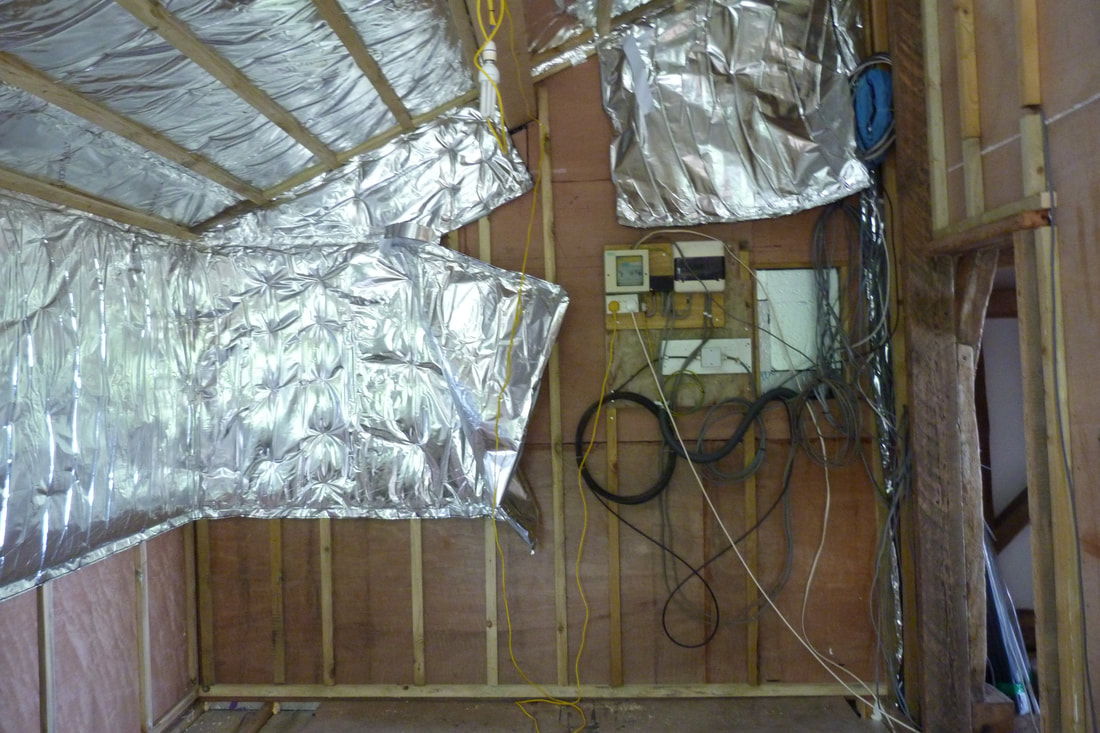
Internally we progressed with lining out the interior walls and wiring the electrics. Under the rafters and over the walls in the Bedroom we battened, fitted multi-foil, then cross battened. In the bedroom we finished with plasterboard but swopped it around in the Kitchen / Bathroom to finish with Ply under the plasterboard to provide a wall to fix to. Even as we converted our ideas of preferred practice changed.
The main fuse-boards were sited here, making this a busy area. This end wall will be a built-in wardrobe, so it suited well. The over engineering included the electrics, and we fitted two current wiring standard fuse-boards so the circuits could be split into four areas, as opposed to the two required by regulations. The wall contains multiple ducts and conduits, some empty, to give future redundancy if required.
The main fuse-boards were sited here, making this a busy area. This end wall will be a built-in wardrobe, so it suited well. The over engineering included the electrics, and we fitted two current wiring standard fuse-boards so the circuits could be split into four areas, as opposed to the two required by regulations. The wall contains multiple ducts and conduits, some empty, to give future redundancy if required.
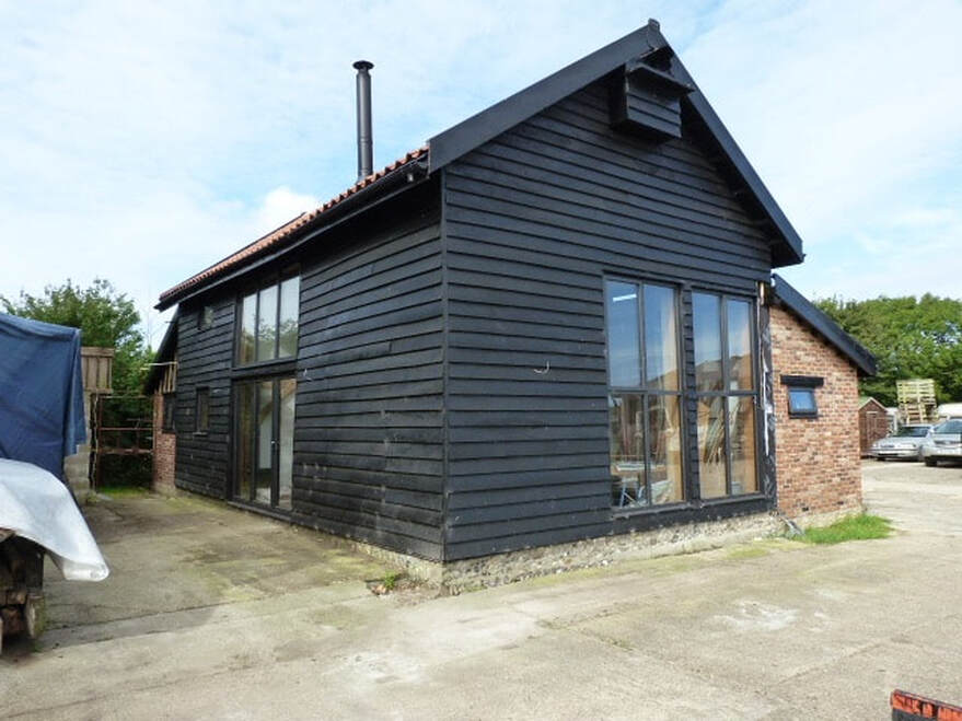
Externally we got on well with most cladding completed, and the adjacent building remains removed. At this point the rainwater drains are still to install, and again this exceeds the current requirements by a figure of two. All the gutters are only required by building regs to have one downpipe, but I fitted two on the likelihood that one in fifty-year torrential rainfall is now occurring annually. I am particularly pleased with the flint base quite evident in this photo. External lighting is still to fit in this photo, as are the downpipes.
The Barn 2016
We are pretty much on the home straight now, with moving in at the end of this year, avoiding the temptation to move in early as it makes finishing that much harder. There are still big fit out items to complete, but now in a warm weathertight environment.
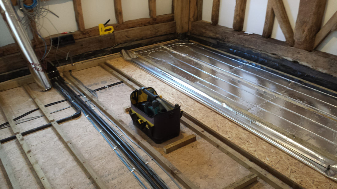
Above is the underfloor heating install, here in the Study (which is also Bedroom 3). The floor construction here is DPC and 100mm Celotex over the concrete slab, then the OSB sub-floor on the left had side. 2” by 2” timber is over this, giving a floor void for services and the heating pipe feeds, capped by another layer of OSB flooring. Over this is laid single layer foil, then the polystyrene / foil heating pipe layer, with battens in between the heating pipe sheets. Normally the floor is loose laid on top, but I was unhappy with this idea, so fitted the batten to provide a solid fixing. Not shown is the chipboard flooring to finish off, this was painted matt black on the underside to absorb the heat better. Screwing down the floor was nerve racking as a single screw in the wrong place could mean an extra week’s work replacing a pipe loop, but in the event, there were no mishaps.
The 150mm gap between heating pipes is non-standard, it normally being wider. I was unhappy with the design BTU with a wider spacing and yet again wanted to over engineer it to make sure the heat output was more than adequate.
So, we ended up with a totally bespoke non-standard heating system, but we have engineered out all the shortcomings of underfloor heating concerning latency, heat retention and speed of response.
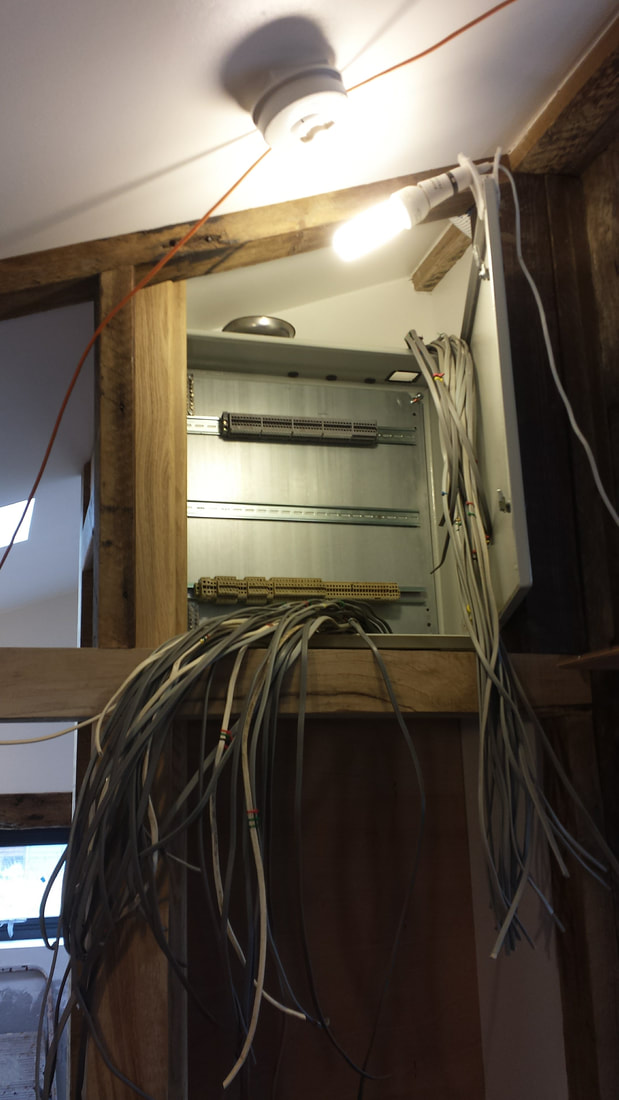
This is Node Zero, the hub of the home automation, sited in the high-level Hall cupboard. More detail elsewhere, but all outside and Lounge lighting pass through here, together with all sensors and switches. It ended up with quite a lot of cables, and a book of the terminal designations, but it gives total flexibility now and, in the future, and allows individual cause and effect flexibility with hard wired reliability – effectively an old-fashioned computer! Wireless control interfaces have been added to this, and Alexa added to that.
Note the smoke detector on the ceiling. There are three at key locations, all mains powered with battery back-up, and interconnected.
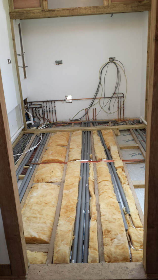
This is a view of the Kitchen floor, with the Larder at the back. In view is the 2” services void containing cabling and pipework. Over this will be an OSB sub-floor, underfloor heating pipes, then a chipboard floor as per the main Barn.
At low level in the Larder on the left is the drain for the Washing Machine and En-suite sink, on the right the drain for the Dishwasher. In between are the manifolds for the cold-water supplies, all individually piped to the respective outlet. The four pipes in the centre are hot water feeds to individual outlets. This arrangement minimises the effects on pressure of operating multiple outputs at once, i.e. flushing the toilet does not affect the Shower. It also allows individual isolation in the event of a leak or for maintenance. A loop on the left-hand side allows for the fitting of a Water Softener, with the exception of the Kitchen cold water feed, which is double filtered.
The hole in the wall is to allow for pipework to be added for the outside Combi boiler yet to be installed.
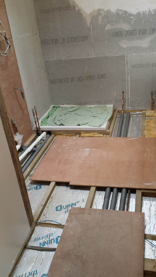
This is a view of the Bathroom during the build. The Shower area is lined with waterproof Hardiebacker board, with a false wall yet to be erected on the left-hand wall to give recessed cupboards and a hidden cistern. The shower base is partially reset into the floor, whilst the bath not seen to the right is recessed into the floor joists. The design allows for full access to all pipework after completion and all outlets are fitted with individual maintenance valves. The left-hand wiring is for two hidden shaver points at both high and low level, as well as led lighting. The design allows for future maintenance and all pipework is accessible and adaptable, with the shower in particular able to be replaced at some future date without any damage to the tiling.
Incidentally, I originally opted to try plastic plumbing, keen to keep up with the latest trends. Having installed a length of 20mm pipe I rapidly changed my mind. It was impossible to either bend or lay flat, so I quickly changed back to copper.
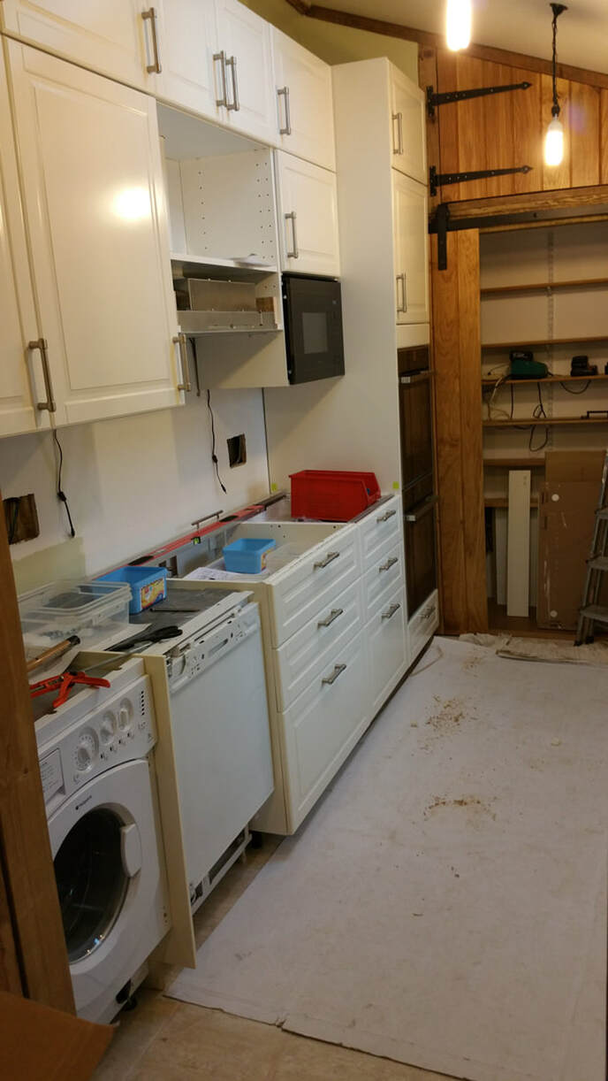
The left-hand side of the Kitchen is shown here. To overcome the lean of the Barn wall behind the units I had to build a second vertical wall over the timber frame from the floor to the top of the units. The IKEA kitchen units are highly recommended, the wasted space of the plinth is smaller than other units and the cupboards are bigger as they don’t have false backs and allow free access to services behind. Just be aware that you need to buy the built-in appliances from IKEA as standard appliances are not a good fit. We purchased another make for the dishwasher and the fit of the door is a compromise.
The hanging cables under the top cupboards are for hidden lighting over the worktop. Bad idea! When fitted over the black granite worktop it reflected the underside of the units onto the worktop, so only do this with non-reflective worktops. We scrapped all this lighting.
The Larder is shown at the far end, this tidied up what otherwise would have been two difficult to utilise corners. Larders are a lost essential element to Kitchens and are a highly efficient feature. Ours houses all the water terminations and manifolds, boiler pipework, drains, and water softener, as well as all the normal storage such as food and appliances.
The large holes in the walls are for sockets. When wired the exact locations were unknown so a large plus and minus tolerance was allowed. Once the worktop is in and the tile size known the exact locations to fit in with the tiles can be calculated.
Kitchens are complicated. Apart from electrics and plumbing, the unit fit varies depending not only on the units themselves but also the infill panels. There is much to calculate, check and double check, and a lot to be said for loose fitting the units before any fixing commences. Selecting appliances to suit is also a nightmare. The IKEA microwave will only fit a deep cupboard and other microwaves are too deep to fit a standard wall cupboard. However, IKEA wall cupboards are deeper than standard and we found a NEFF microwave that would fit the IKEA wall cupboard, but it took some looking!
In the plan all appliance sockets are concealed in cupboards and not always in inaccessible places like behind the appliance itself. Note under the spirit level are two such points, and the oven switches are in the Larder. This gives a clean tiled finish with only the necessary sockets visible.
Here we have a view of the Hall from the Lounge. The three bays had been removed in the past to make a doorway. The left-hand bay has now been replaced as a wall to the Kitchen and the two centre bays left open to the Hall. The two green oak uprights have blended in and the horizontal beams fitted and the uprights above the doorway tidied up. It is a job to remember this wall is totally new.
Note we are still running on temporary lighting at this time, although some sockets appear in use.
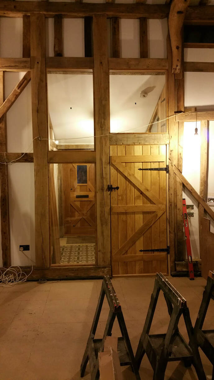
We had intended to obscure glaze the panels to give privacy from the front door, but the clear glazing fitted gives an impression of space.
This photo clearly shows a door. These were sourced from the midlands and I think are European oak. We ordered a selection of standard sizes then cut them to fit our doorways. It was a mixture of fitting oak lining to reduce the doorway if required and adding oak jams after installation. They were kept in the Barn for a few months to acclimatise but have in some cases shrunk a little since install. They were sanded, given a coat of satin polyurethane, another light sanding, then a final coat. The ironwork was sourced from ironmongers via eBay, the hinges being hand made. All screws required a pilot hole drilling then fixed with good quality stainless self-tapping screws. They were quite easy to fit once the first one was worked out, but of course every one is a different size and hardly any door frames are square or vertical.